OWE Cable Installation
Offshore wind energy (OWE) cable installation is a critical part of the process for bringing offshore wind farms online. It involves laying and burying high-voltage cables on the seabed to connect the wind turbines to each other and to the offshore substation, which then transmits the electricity generated to the onshore grid.
Types of Installation
Simultaneous Lay & Burial
One Cable Lay Vessel (CLV) lays and buries the cable in a single operation.
Saves money on daily operational costs.
The process is slower and, therefore, needs a longer weather window which could complicate construction schedules.
Post Lay Burial
A Cable Lay Vessel (CLV) lays the cable on the seabed. It is then buried via a separate operation (usually by a different vessel).
Two vessels required which increases cost.
There is a lot of flexibility with regard to making the full use out of weather windows.
Installation Steps
While cable installation methods vary based on project conditions and timelines, installation generally follows the below steps.
Seabed Preparation
Prior to any submarine cable installation, the route must be cleared of any obstacles that could interfere with the installation and burial operations, or cause post-installation damage to the cable.
-
Out-of-service (OOS) cables may present obstacles for export and array cable burial. If these cables are located in the cable corridor, they are usually cut at points on either side of a new cable’s installation corridor and the section crossing the cable corridor is removed and scrapped/recycled onshore. The remaining free ends of the OOS cables are usually buried.
-
While cable route planning is meant to mitigate environmental impact by micro-routing cables around boulders, sometimes it is necessary to remove boulders for safe and effective burial. Often a boulder plow is used. This mechanism pushes superficial boulders to just outside of the cable corridor. A boulder pick may also be used to pick up and move larger boulders.
-
The last route clearance activity prior to cable installation is the Pre-Lay Grapnel Run (PLGR). This activity is designed to remove any other obstructions that may have been deposited since the surveys, or perhaps were not known about previously. Items typically removed during PLGR operations are wires, ropes, abandoned fishing gear, pipes and tubes, and general debris. It is standard practice to undertake this operation immediately prior to the cable lay operation.
2. Export Cable Installation
Once the cable route has been cleared, the cable installation operations can commence. Export cables are significantly larger, heavier, more expensive and much longer than array cables, running from the offshore substation to the shore landing. This distance spans both state and federal waters which means that the export cable falls under both permitting jurisdictions.
-
The installation of the shore-end of an offshore wind export cable involves several steps:
Preparing the landing site: Before the cable can be installed, the landing site onshore must be prepared. This involves clearing and grading the site, and installing any necessary infrastructure, such as cable ducts, trenches, or conduit.
Trenching: A trench is excavated along the shore from the landing site to the point where the cable will be buried beneath the sea floor. The trench is typically dug using specialized equipment, such as a jet plow or trenching machine, and is designed to protect the cable and ensure that it is buried at the appropriate depth.
Cable pull-in: The offshore end of the cable is connected to the onshore cable, and the cable is then pulled through the trench using specialized equipment, such as a cable laying vessel or tug boat. The cable is typically protected during the pull-in process by a series of rollers and tensioning devices.
Cable termination: Once the cable is pulled into the trench and connected to the onshore cable, it is terminated and connected to the onshore electrical grid. This involves installing a cable termination joint, which connects the cable to a substation or switchgear, and then testing the connection to ensure that it is functioning properly.
Backfilling and reinstatement: Once the cable is installed and terminated, the trench is backfilled with soil or other materials, and the shore is reinstated to its previous condition. This typically involves re-vegetating the area and installing any necessary erosion control measures.
The industry standard for trenching is Horizontal Directional Drilling. Horizontal directional drilling (HDD) is a technique used to install offshore wind export cables beneath the seabed without the need for traditional trenching methods. HDD involves drilling a horizontal borehole beneath the seabed from the shore to the offshore location where the cable will be connected, and then pulling the cable through the borehole. This allows the cable to be buried beneath the seabed without disrupting the seabed surface or damaging the marine environment.
-
The main offshore wind export cable is typically laid using a specialized vessel known as a cable laying vessel (CLV). The cable laying process involves several steps:
Cable loading: The cable is loaded onto the cable laying vessel from a cable storage barge or facility. The cable is typically loaded onto a cable drum on the vessel, which is used to spool the cable out during installation.
Cable laying: The cable laying vessel then travels along the predetermined route, laying the cable onto the seabed as it goes. The cable is typically fed off the cable drum and into a chute or other installation mechanism that guides the cable into position on the seabed.
Cable burial: Once the cable is laid on the seabed, it may be buried using specialized equipment such as a jet plow or trenching machine. Burying the cable helps protect it from damage due to fishing activities or other hazards, and can also help mitigate any potential environmental impacts.
Cable protection: In addition to burial, the cable may also be protected using specialized protection systems such as rock berms, concrete mattresses, or other forms of seabed protection.
Cable termination: Once the cable is fully laid and protected, it is terminated and connected to the offshore substation or wind turbine. This involves installing a cable termination joint, which connects the cable to the substation or turbine, and then testing the connection to ensure that it is functioning properly.
-
Offshore wind cables are connected to offshore substations through a process called "cable termination". This process involves connecting the end of the wind turbine or inter-array cable to a specialized connector that is attached to the substation.
The cable termination process typically involves the following steps:
Preparing the cable end: The end of the cable is first prepared by stripping away the outer insulation and shielding layers to expose the individual conductors.
Installing the connector: The connector is installed on the end of the cable using specialized tools and techniques. The connector is designed to fit with the substation connector, ensuring a secure and reliable connection.
Testing the connection: Once the connector is installed, it is tested to ensure that it is working properly and that there are no faults or issues with the connection. This involves using specialized equipment to measure the electrical properties of the connection and to verify that the signal is being transmitted correctly.
Securing the connection: Once the connection is tested and verified, it is secured using a variety of methods, including mechanical fasteners, clamps, and adhesives. This ensures that the connection remains secure and stable, even in harsh offshore conditions.
Overall, cable termination is a critical process in offshore wind energy development, as it ensures that the power generated by the wind turbines is efficiently transmitted to the offshore substation and ultimately to the onshore electrical grid.
3. Array Cable Installation
Array cables join the individual offshore wind turbines together and connect the strings of turbines to the Offshore Substation Platform (OSP), which are subject to developer-specific engineering constraints.
-
Offshore wind energy inter-array cables are typically laid and buried using a similar process to the main export cable, but on a smaller scale. The inter-array cables connect the wind turbines within the wind farm to each other and to the offshore substation. Here are the steps involved in laying and burying inter-array cables:
Cable preparation: Inter-array cables are prepared for installation onshore, which includes checking for any defects, splicing together sections of cable as necessary, and adding any necessary accessories such as joints or terminations.
Cable loading: The cable is loaded onto a cable laying vessel, which typically has a smaller cable drum than a vessel used for the main export cable.
Cable laying: The cable laying vessel travels along the predetermined route, laying the cable onto the seabed as it goes. The cable is typically fed off the cable drum and into a chute or other installation mechanism that guides the cable into position on the seabed.
Cable burial: Once the cable is laid on the seabed, it may be buried using specialized equipment such as a jet plow or trenching machine. Burying the cable helps protect it from damage due to fishing activities or other hazards, and can also help mitigate any potential environmental impacts.
Cable protection: In addition to burial, the cable may also be protected using specialized protection systems such as rock berms, concrete mattresses, or other forms of seabed protection.
Cable termination: Once the cable is fully laid and protected, it is terminated and connected to the offshore substation or wind turbine. This involves installing a cable termination joint, which connects the cable to the substation or turbine, and then testing the connection to ensure that it is functioning properly.
-
Offshore wind array cables are connected to the offshore substation using specialized cable termination joints. These joints are designed to connect the individual inter-array cables to the substation, allowing the electricity generated by the wind turbines to be collected and transmitted to shore.
Here are the general steps involved in connecting offshore wind array cables to the offshore substation:
Cable preparation: The inter-array cables are prepared for termination onshore, which includes checking for any defects, splicing together sections of cable as necessary, and adding any necessary accessories such as joints or terminations.
Cable routing: Once the inter-array cables are laid and buried, they are routed to the offshore substation. This may involve passing the cables through cable protection systems such as rock berms or concrete mattresses.
Cable termination: The inter-array cables are connected to the offshore substation using specialized cable termination joints. These joints are designed to provide a secure and reliable connection between the cables and the substation.
Testing: Once the cable termination joints are installed, they are tested to ensure that they are functioning properly. This may involve testing for electrical continuity, insulation resistance, and other parameters.
Commissioning: Once the cable connections are verified and tested, the offshore substation is commissioned, which involves bringing it online and ensuring that it is operating properly. This typically involves a range of tests and inspections to verify that the substation is functioning as intended.
-
Burial methodology: pre-lay burial/route and boulder clearance.
Soil type: can trench in soil up to stiff/hard clays
Burial depth: commonly 1m to 1.7m (or more depending on sediment conditions)
-
Burial methodology: pre- or post-lay burial/de-burial.
Soil type: Various, up to 200 kPa if configured for cutting, 80kPa as standard.
Burial depth: up to 5m if possible depending on soil types, 2m is more commonly achieved.
-
Burial methodology: pre-lay burial
Soil type: Various
Burial depth: varies depending on the number of passes.
-
Burial methodology: simultaneous. lay and burial.
Soil type: various but works well for deep burial in soft sediment in shallow water.
Burial depth: up to 10m or more depending on sediment conditions.
-
Burial methodology: simultaneous lay and burial.
Soil type: sand, silt, gravel
Burial depth: commonly up to 2-3m, very large machines can achieve 5m or more.
-
Burial methodology: simultaneous lay and burial.
Soil type: from approximately 5 kPa to 350 kPa.
Burial depth: up to 3m.
-
Burial methodology: simultaneous or post-lay burial
Soil type: cohesive sands in jetting more, soft rock in chain cutting mode.
Burial depth: 3m
-
Burial methodology: post-lay burial
Soil type: sand, silt, gravel
Burial depth: 3m
The types of cable installation tools used differ based on project needs and sediment conditions.
Other Cable Protection Measures
While cable burial is always the primary method of cable protection, there are conditions where adequate burial cannot be achieved. These include: (1) hard soils or the presence of bed rock, glacial tills, large boulder fields, etc., (2) geographic features such as slopes and subsea ravines, (3) cable and pipeline crossings, and (4) proximity to structure. In the event that any of these conditions occur along the cable route, additional protection measures may be used.
-
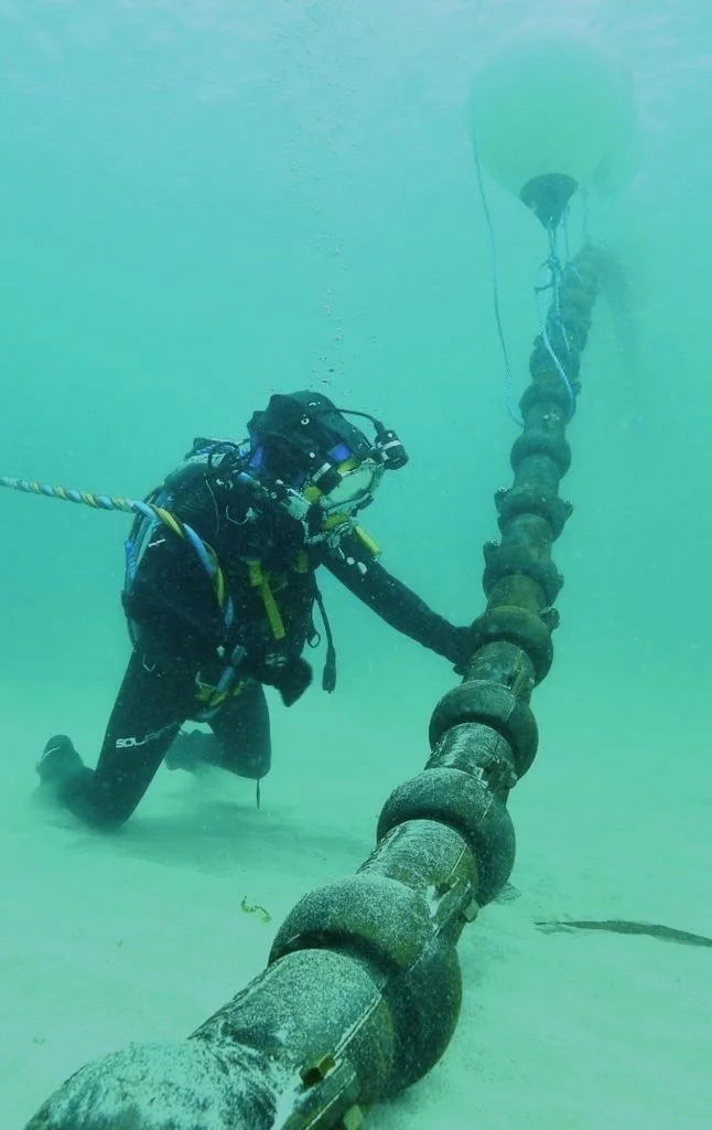
Articulated Split Pipe
These are short, cast iron sleeves applied to the cable during surface lay. These sleeves act as additional armor, protecting the cable against crushing, impact damage, and abrasion. Split pipes are commonly used at shore ends and where the cable meets offshore wind structures.
(Photo: Wind Systems Magazine)
-
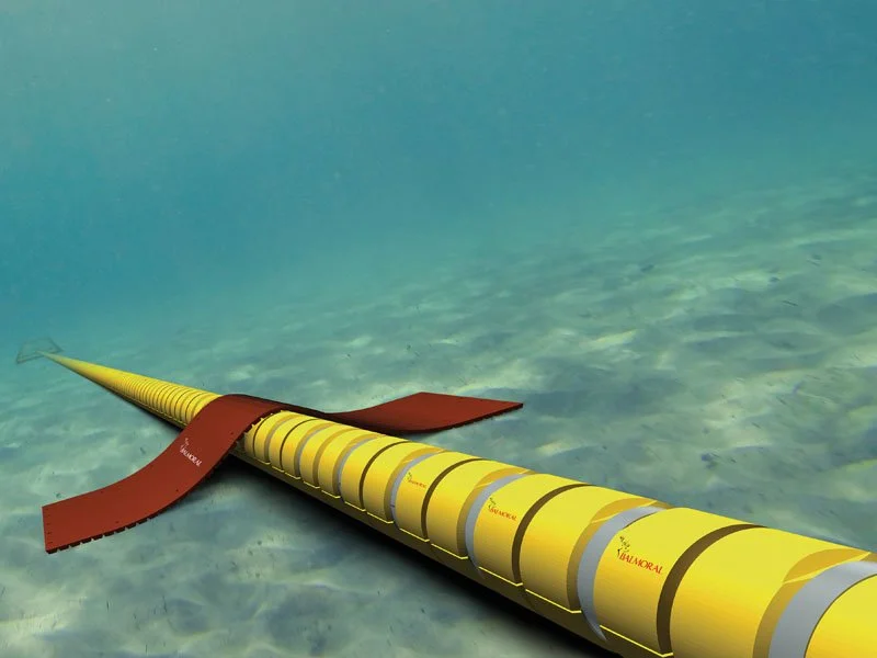
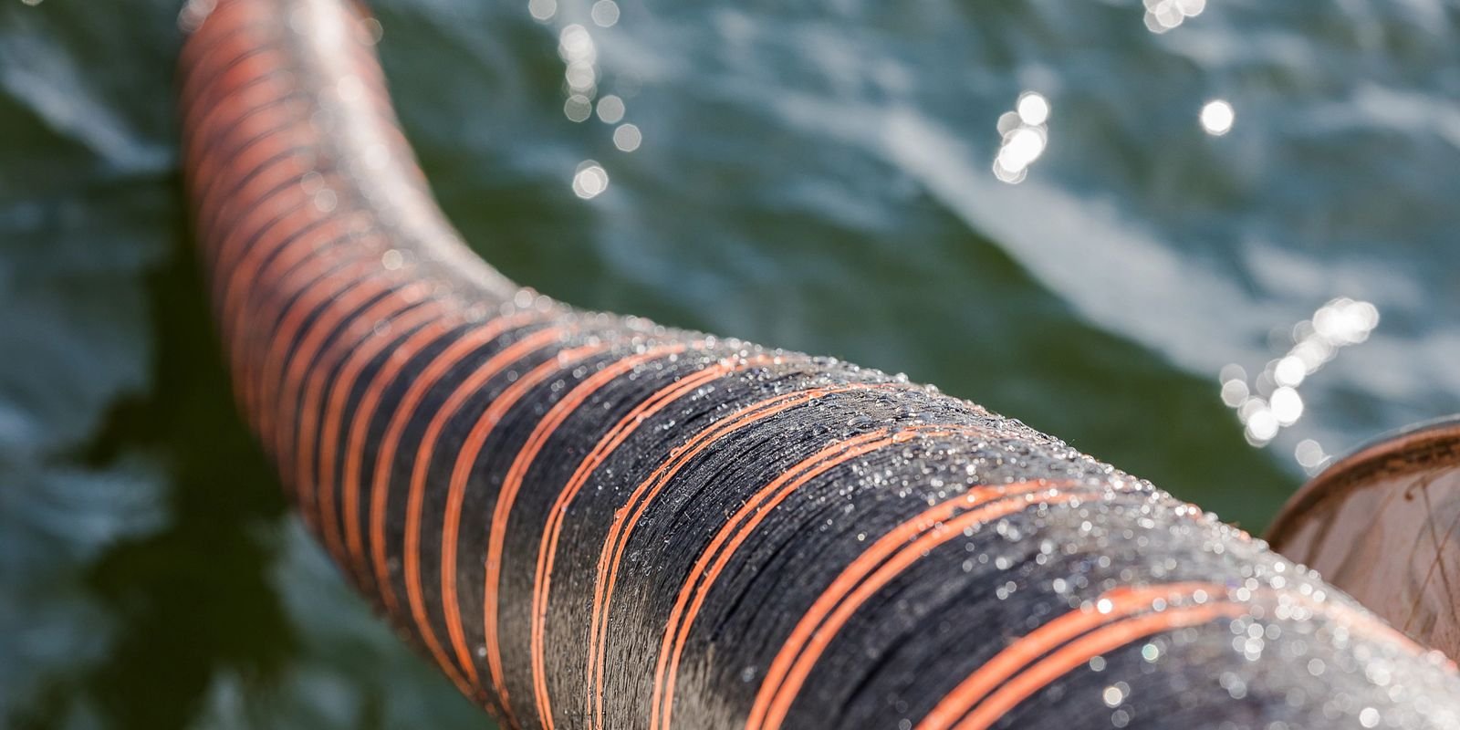
Uraduct (or simular)
Uraduct is a Polyurethane system that clamps onto areas of a cable to provide protection from abrasion and impacts. This system is most commonly used at cable crossing where the cable is sandwiched between concrete mattresses.
(Photo: Balmoral DURAGUARD)
-
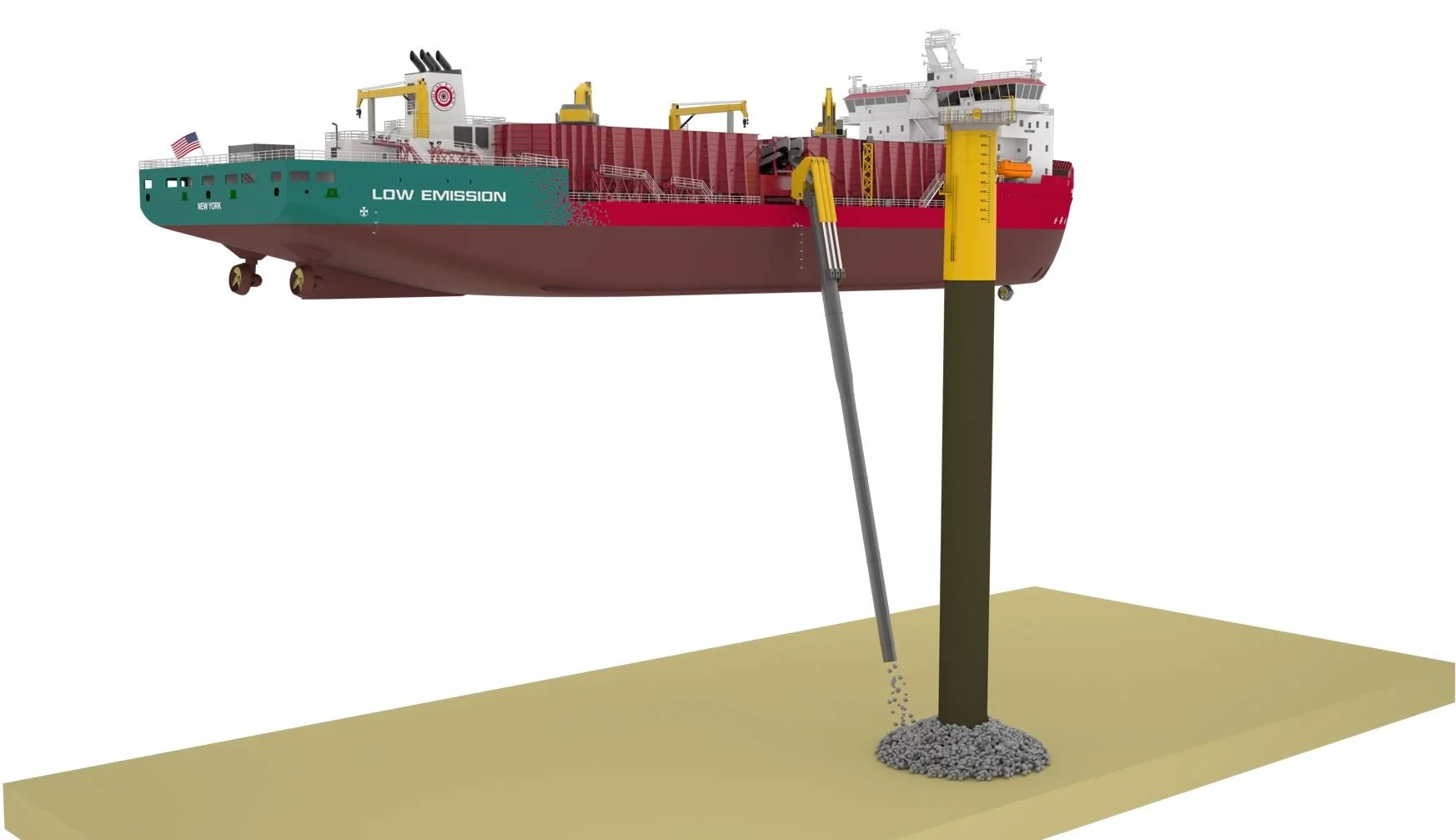
Rock Placement
It is impossible to bury the cable in the area immediately around the turbine base. Therefore, after split pipes of Uraducts are applied, rocks many be installed around the base of the turbine to protect from scour and ensure that the cable is not exposed.
(Photo: Huisman, Offshore Energy Today)
-
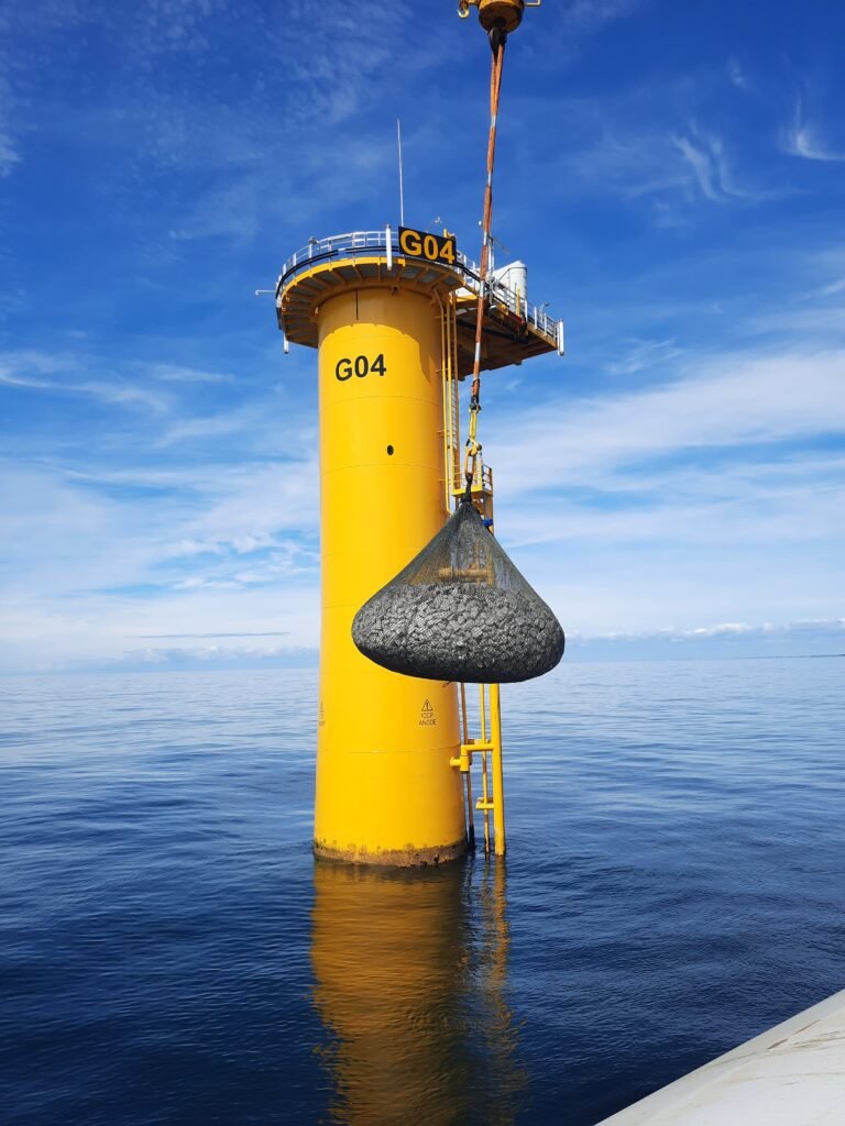
Filter Bags
Filter bags are rock-filled mesh bags that are used for scour protection around the base of the turbine and as cable protection at cable crossings. They conform well to the shape of the seabed and may create habitat.
(Photo: Ridgeway, offshore-energy.biz)
-

Concrete Mattresses
Concrete mattresses are the most commonly used cable protection method at cable crossings and in areas where the cable cannot be buried at its target depth. A concrete mattress is placed between the cable and the asset it is crossing and then additional mattresses are placed on top to protect the cable. Many of these mattresses are designed with tapered edges so that fishing gear can be towed over them.
(Photo: TDN Energy, Fleximats)
-

Frond Mattresses
Frond Mattresses are combined with concrete mattresses to reduce scout and sediment erosion. The fronds capture and deposit sediment and provide habitat for marine species.
(Photo: Renewable Technology)
Additional Resources and Page Sources